Hardware Accelerated Image Stitching: GPU vs FPGA
Overview
Image stitching is a process where two or more images with an overlapping field of view are combined. This process is commonly used to increase the field of view or image quality of a system. While this process is not particularly difficult for modern personal computers, hardware acceleration is often required to achieve real-time performance in low-power image stitching solutions.
Implementation
A standard image processing pipeline for image stitching involves five main steps: feature detection, feature description, feature matching, image transformation, and image mixing. Feature description is sometimes included in the feature detection algorithm, but this depends on the feature detection algorithm. In this project, the Speeded Up Robust Features(SURF) algorithm was used for feature detection. Since the SURF algorithm includes a feature description algorithm, the two logical blocks have been combined in the graphical representation. A figure outlining a basic image stitching pipeline for two image sources can be seen below.
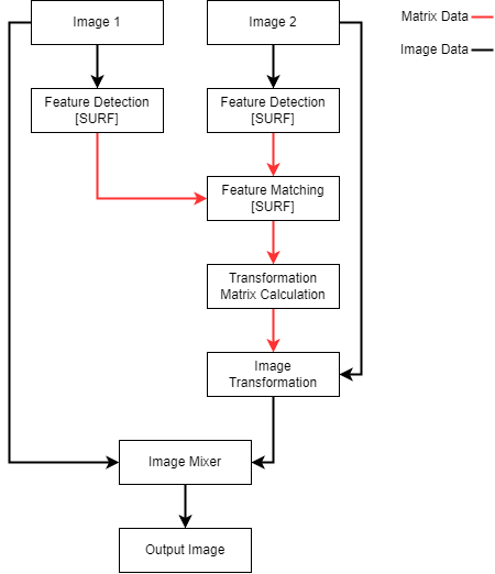 Figure 1: Image Stitching Pipeline
Feature detection
Feature detection is the process of detecting points which are locally unique in a consistent manner. It's important that the points detected are consistently detected in overlapping field of view images even when the images are taken from different perspectives. If feature points can be consistently detected they can be found in unique images, used for object recognition, or other advanced purposes.
Feature description
Feature description, otherwise known as feature classification, involves the description of the locally unique points in a manner that should be consistent regardless of noise, translation, or other factors. While some feature detection algorithms don't include a corresponding feature description algorithm, the algorithm used in this project(SURF) does.
Feature matching
Feature matching involves the comparison of classified feature points from multiple images to find similar points in distinct images. These matched pairs of feature points are used to calculate the transformation matrix used to transform two images to a common coordinate system. An absolute minimum of four pairs of points is necessary for this calculation, but generally more points tend to provide a better result.
Image transformation
The image transformation portion of the pipeline is responsible for calculating the transformation matrix required to convert both images to a common coordinate system. This process is performed using the matched pairs of feature points from the previous step and can be broken down into three steps: matched pair selection, transformation matrix calculation, and error calculation. Point selection can be performed randomly or algorithmically and involves selecting a set of matched pairs of feature points for the calculation. Calculating the transformation matrix is commonly performed using either the homography or fundamental matrix. The homography matrix was used in this implemenation and only requires four pairs of points. Calculating an error value to associate with the calculated transformation matrix generally uses the remaining matched pairs of feature points not associated with the current iteration of the transformation matrix calculation. After calculating a number of transformation matrices and their corresponding error, the transformation matrix with the lowest error is often selected.
Image mixing
Image mixing uses the originally supplied images and at least the previously calculated transformation matrix. Depending on the output format of the system, the image transformation portion of the pipeline may involve additional transformations. Once both images have been appropriately transformed, the output pixel at any given location in the output frame needs to be determined. It is the responsibility of this component to make that determination.
FPGA
For the FPGA accelerated portion of this project, acceleration was used for image preprocessing and the feature detection portion of the pipeline. The choice to accelerate only this portion of the pipeline is mainly due to the large resource utilization required for parallelizing the application of all the different SURF filters being applied to a common set of data. Once the feature point locations have been found, they are passed with the calculated integral image to the systems DDR memory via DMA. The remainder of the processing performed by the image stitching pipeline is performed using the FPGA's integrated hardcore ARM processing subsystem. A high-level architecture of the FPGA feature detection portion of the pipeline can be seen in the figure below.
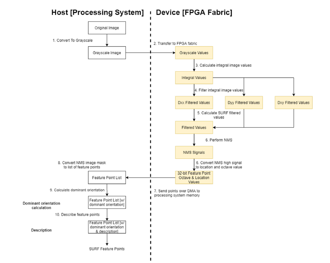 Figure 2. FPGA SURF Algorithm Dataflow Diagram
Once the processor receives the feature point locations and their associated filter widths along with the integral image, feature point description can occur. Feature points are appended to a linked list and the feature points found in the exclusionary region around the border of the image are discarded. The number of linked lists for the feature points retained during processing is equal to the number of image sources used. Once all the feature points have been described for at least two input images, the feature point lists are supplied to the feature matching code.
Feature matching is performed using a brute force comparison of all points between the two linked lists of feature points using a relative matching criterion. The brute force comparison process tracks the two lowest feature point description errors using two variables. When the two lowest errors fulfill the relative matching criteria after iterating through all possible matches, the feature point associated with the lowest error and the feature point being considered are considered a match. A match is indicated using a nonzero pointer value stored in the linked list struct associated with each feature point. Once all feature point matches have been found, the homography calculation is performed using RANSAC.
After the homography matrix is found, it is supplied to the host computer via a UART serial communication link. The mixing of the two images is then performed on the host computer using OpenCV and displayed to the user in a new window.
GPU
For the GPU design, the CUDA library was used for accelerating the algorithm on an Nvidia graphics card and OpenCV was used to read the input images and output the stitched image. The program was written in C++ with most of the code being C compliant. The SURF algorithm, feature point matching algorithm, and homography calculation algorithm were written from scratch originally as a proof-of-concept implementation to be executed on a CPU. Writing these algorithms from scratch also allowed for easier porting to the GPU-based hardware acceleration. Additionally, some of the code written for the proof-of-concept CPU version of the program was used in the FPGA implementation.
The portion of the pipeline that was accelerated on the graphics card was the feature detection portion of the pipeline. This includes the integral image calculation, SURF image filtering, and non-maximal value suppression. The NMS image the GPU calculates is a mask image which gets converted to a list of feature points on the host computer so that it can be used by the remainder of the image stitching pipeline. A graphical representation of the high-level architecture of the GPU implementation can be seen in the figure below.
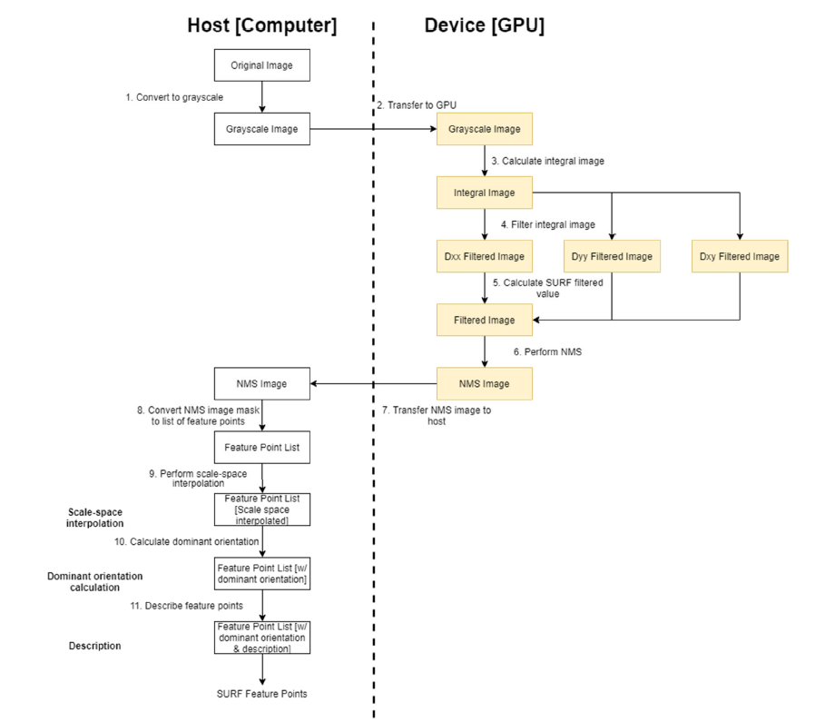 Figure 3. GPU SURF Algorithm Dataflow Diagram